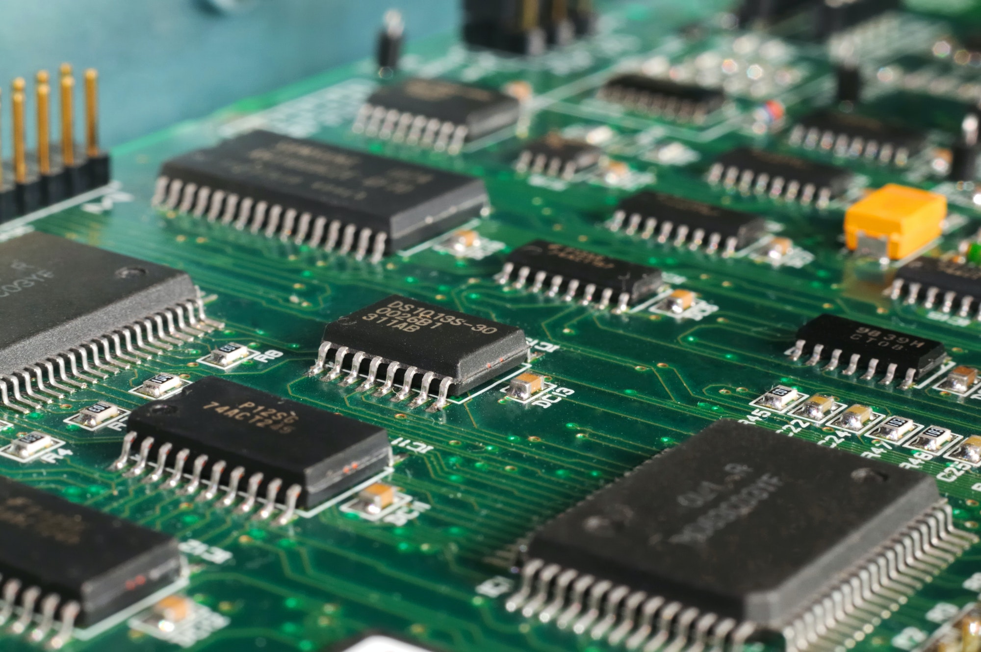
A printed circuit board, PCB, is mechanically support electronic components that
connected by signal traces that etched from copper foil over a non-conductive
board. A PCB already with components is called PCBA (PCB Assembly). Kingboard
(KB) and Shengyi (SY) are PCB laminate board provider in China.
Single-sided PCB
? Commonly use XPC or FR-2 as PCB base material that one side with copper
foil.
? XPC is the lowest cost.
? FR-2 can provide better mechanical and electrical characteristic than XPC.
? Material thickness can be 1.0, 1.2 or 1.6mm while 1.6mm is most popular for
consumer electronic product if product size is not a concern.
? Place all components on one side of PCB as possible. SMD component placed
on the copper side for soldering while lead type component placed on the
opposite side.
? Carbon jumper can be printed over copper as part of circuitry for connecting
copper traces.
? If bonding die IC is used, the PCB should be Ni-plating or better with Goldplating.
Single-sided PCB with Carbon PTH (plate through hole)
? All materials same as single side PCB.
? Carbon circuit is printed on the opposite side of copper side, and connects
to copper side by Carbon PTH. Normally the printed carbon side is used for
keyboard.
? Carbon PTH cost is cheaper than Copper PTH that normally used in doublesided
PCB.
Double-sided PCB
? Normal use FR-4 as PCB base material with 2 sides of copper foil. Material
CEM-3 can be used when high power circuitry is need.
? It provides better mechanical and electrical characteristic performance for
precise electronic component and circuitry, such as high frequency RF.
? Material thickness range from 0.6, 0.8, 1.0, 1.2 or 1.6mm while 1.0 and 1.6mm
are most popular.
? Both sides circuit are connected by Copper PTH.
Multi Layer PCB
? The base PCB material is normally FR-4 but with more copper laminated layers
on both sides. It can be 3, 4, 6, 8 layers.
? Much expensive than 2-layer PCB.
? It can provide smaller product size as components are closely place together
and the connection traces can go in under layer that save more space.
? Below shows the construction of multilayer PCB (Photo from www.pcbgogo.com)
Flexible PCB
? Flexible PCB (FPC) with the flexible nature of the connection for reduction of
space, weight when compare to a rigid PCB.
? It can be used to replace electrical wiring, or can be soldered with components.
? FPC can be divided into single layer, double layer or multi- layer circuits. The
main dielectric substrate film commonly used is Polyimide (PI) with electrical
conductors of copper adhered on it. The Copper PTH technology is also
applicable for multi-layer PCB.
? The main advantage of FPC is greater freedom in the design as it can adapt to
small or irregularly space, and light in weight. Also it is more reliable and longlasting
than rigid PCB as less subjected to continuous vibration and stress.
? The main disadvantage is the high initial tooling and setup cost. Also it is
difficult for repairing or modifying the PCB after fabrication.
? Below are FPC example (Photo from www.unitcircuits.com and hitechcircuits.com).
LCD
? LCD (Liquid Crystal Display) is a thin glass laminated with polarizer on top and
bottom while Liquid crystal in-between.
? It gets display by use of liquid crystal light-modulating under electronic current
and combined with polarizers.
? The typical glass thickness used is 0.7mm or 1.1mm.
? LCD does not emit light by itself. For view under dim light, a backlight module
is placed on the backside of LCD.
Segment and Dot Matrix LCD
? Segment LCD is the display content in form of predefined shape for the exact
display graphic or character. Generally numeric segment can be formed by 7,
14 or 16-segment. Also custom build segment pattern is possible.
? Dot matrix LCD is the display content are formed by numbers of same size
pixels. The required display graphic or character is formed by combination of
the pixels.
Passive LCD
? Passive LCD uses grid of vertical and horizontal conductors to create an image.
Each pixel is controlled by an intersection of two wires in the grid. By
change the electrical charge at an intersection, the color and brightness of
the corresponding pixel can be changed.
a) TN
? Twisted Nematic (TN) is the basic type LCD where liquid crystal is twisted 90°.
? It usually provides black characters on a gray background.
? It is the lowest cost, but has the lowest visual quality and narrower viewing
angle.
b) HTN
? HTN (High Twisted Nematic) displays with a higher molecular twist (usually
110°) than TN (90°) offers wider viewing angles and better contrast.
? HTN characteristics close to STN technology, with marginal extra cost over TN.
c) STN
? Super Twisted Nematic (STN) LCDs have a twist between 180 and 270 degrees.
? The more angle twists, the higher the contrast.
? It provides wider view angle and better contrast than TN type at moderate
pricing.
d) FSTN
? Film compensated Super Twisted Nematic (FSTN) displays that adds a film to
the STN that compensates for birefringence effect.
? It allows a black and white display at higher contrast and wider viewing angle.
? It is the more expensive compare with TN and STN, but better viewing angles
and contrast that STN.
? FSTN is in single coloration for black characters on gray background, while
red, green and blue filters can be added for full color.
Active LCD (TFT)
? Active matrix LCD control each pixel using individual transistor at each red,
green and blue subpixel. This allows pixels to change brightness and color
states more rapidly.
? Active matrix LCD are sharper and more contrast than passive matrix, with
faster response times that eliminate submarining condition.
? Nowadays, color active matrix is the only type of LCD used in LCD / LED TVs,
computer and smartphone LCD.
? Thin Film Transistor (TFT) is an active-matrix LCD flat-panel display provides
the best resolution of all the flat-panel techniques but at most expensive cost.
? Below shows a 1.3 TFT with resolution 240X240 dots.
OLED
? OLED (Organic Light Emitting Diodes) is a new display technology that make
use a series of organic thin films placed between two conductors and emit
fright light when electrical current is applied.
? OLED display have advantages over an traditional LCD display:
? It does not require a backlight as LCD so is can be thinner in construction.
? Improved image quality with better contrast, higher brightness, wider viewing
angle, wider color range, and faster refresh rates.
? Lower power consumption.
? Much durable and operate in a wider temperature range.
? Below is an 0.96 OLED module with resolution 128 x 64 dots.
a) Zebra Connector
? It is used when LCD driving IC is placed on PCB as LCD contact side.
? It is a silicon-based elastomer with conductive filament inside in regular pitch.
? Normally it uses metal frame or plastic frame to form an adequate pressure
between LCD and PCB on the zebra connector for conductive purpose.
? It gives reliable mechanical contact force but cost is higher than heatseal
connector method. It only supports moderate LCD conductor pitch, min as
0.4mm.
b) Heatseal Connector
? It is similar to flexible circuit boards (FPC) while carbon or silver paste are
added on the heatseal connector film surface as conductive.
? The pads of the heat seal are aligned with LCD pads and using a hot bar to
pressurize melt the heatseal conductive adhesive.
? It is most cost effective for the higher volume applications in low-cost electronic
consumer product. It is not suggested use on lower volume and low
interconnection density requirements.
? For better heatseal result, the equipment setup and process should be precise
control, otherwise the heatseal connector service life maybe affected and
result in a shorter product life.
? Finer pitch smaller than 0.4mm is possible.
FPC Connector
? For larger LCD module, such as TFT or FSTN, that commonly comes with COG
(Chip on Glass), TAB (Tape Automated bonding), or COF (Chip On Film) where
the LCD driver IC already fabricated with the LCD panel as a sub-assembly
part for delivery.
? The common method for connecting this type LCD to the PCB is FPC soldering
or FPC connector with various conductive pad pitch.
? Normally the FPC connector in one side contact unless it is a high-resolution
display.
? Below shows FPC connectors for LCD module with PCB connection.